Easy Star 2 - Build Take 2
 My first FPV build was a Penguin V2, it was a larger plane that (as loaded by me) just wouldn’t land! It would glide forever which made it problematic to land at my strip when the winds were in their summer time orientation. Thus, I moved to an Easy Star 2. I purchased the RR (Ready-to-Run) version because it was cheaper when you consider it included the motor and speed controller. The problem with this is that the fuselage was pre-built. The small Easy Star 2 compartment for your battery and RX gear just wouldn’t support FPV gear without having a rats nest of cables that you have to deal with every time you want to swap a battery.
Thus, I purchased the Easy Star 2 Kit Version. From that I built only the fuselage, but not after boring out compartments, testing weight and balance on my existing Easy Star, making nice wiring harnesses for the FPV gear, etc…
So, my new Easy Star 2 equipment:
- In the air
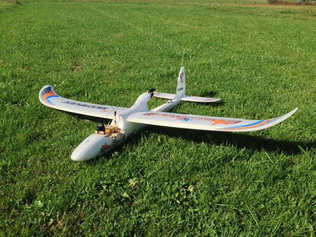
- Easy Star 2
- DragonLink V2 UHF RX
- Dragon OSD+ v2
- ReadyMadeRC 700PRO camera
- CircularWireless Skew Planar TX antenna
- ReadyMadeRC 1.3 GHz 800mw TX
- Ground Station:
- Futaba 8FG Super RC TX connected via the trainer port to the DragonLink UHF TX
- CircularWireless Skew Planar RX antenna
- IBCrazy PepperBox RX antenna
- Sometimes an IBCrazy 3-turn Helical RX antenna
- 2x ReadyMadeRC 900-1.3 GHz RX w/SAW filter upgrades
- EagleTree EagleEyes (video diversity and video splitting)
- ReadyMadeRC DVR1000 - digital video recorder
- ReadyMadeRC 8” LCD mounted on an old camera tripod
- The rest of the ground station (fixed equipment) is mounted on a camera lighting
tripod that extends to 12’ - Peak 900 Jump-Starter (ground station power)
Various pictures of my new Fuselage build, remember I used a lot from the original RR
version:
Dragon OSD+ V2 - Unboxed
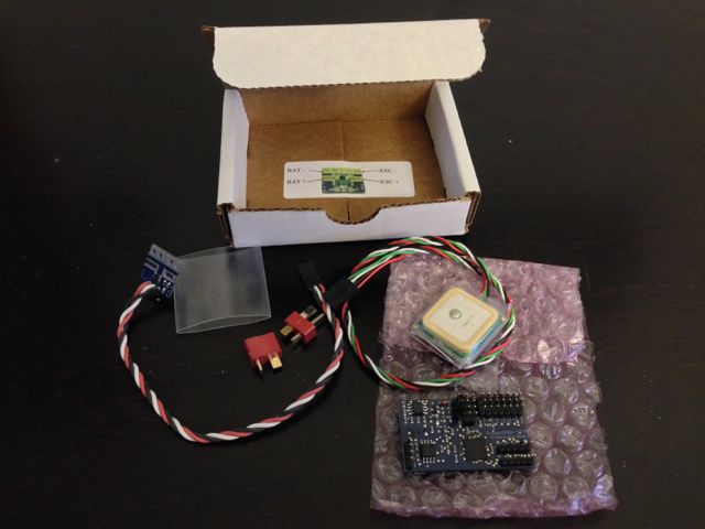
This is fully what you get with the Dragon OSD. This, in my opinion, is not a bad
thing. I made a lot of wiring for my particular setup. With the EagleTree system
coming with all the wires, I used them instead of making custom cables. The EagleTree
system quickly became a rats nest of wiring, almost all of it from excess amount
of wires. Sure, I could have made my own wiring for the EagleTree (more connections)
but I gave into the temptation of a quicker build using supplied cables, as I think
many do.
OSD wired - Getting first GPS fix outdoors
I couldn’t wait until everything was built to see the DOSD on my LCD! I wired up
the bare minimums and took it outside for a go, and it’s first GPS fix.
Current Sensor and Barometer
Later I wound up cutting off the heat shrink tubing from the current sensor and
directly wiring the LC Filter and BEC to it, thus reducing the amount of connectors
and excess baggage of their wires.
The barometer is a standard BMP085. I did heat shrink the unit and cut a little
hole around the barometer sensor.
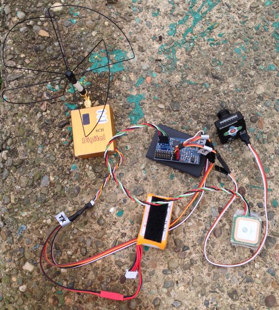
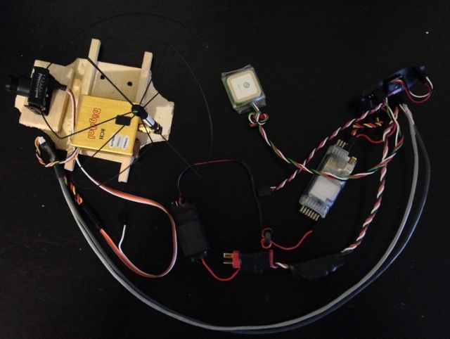
All wired up and working (except servos)
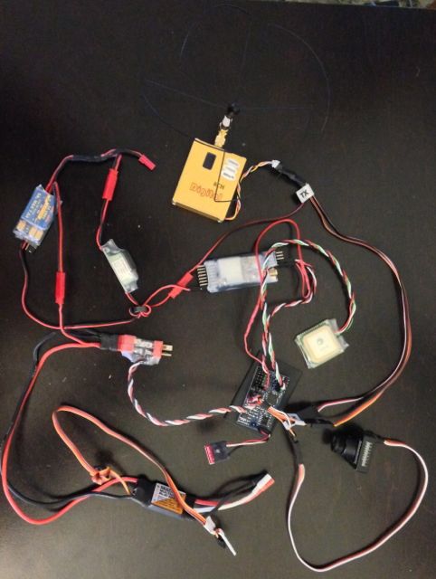
Everything going in my plane is here, wired and working with the exception of the
already mounted rudder, elevator and aileron servos.
I did, however, later change the way the LC Filter and BEC are wired, you will
see pictures of that a bit further down.
Dragon OSD+ V2 - Shrink Wrapped
Now that everything is confirmed to be working, I shrink wrapped the DOSD. This will
make mounting easy, light and give some protection.
Component mounting diagram
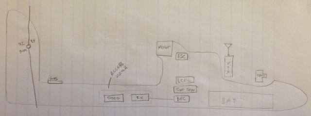
My plan on where everything should go. I put the components roughly in these
locations on the outside of my old Easy Star 2 fuselage for weight and balance
testing. I’m happy to say that with this configuration, I have quite a bit of
freedom on my CG simply by shifting my battery around. I can balance easily with a
2200mAH, 3300mAH and even a 5100mAH battery (which does fit in the main compartment
now that most of the other electronics is in the tail boom)!
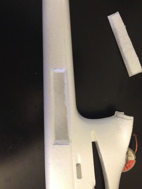
Fuselage with compartments bored out
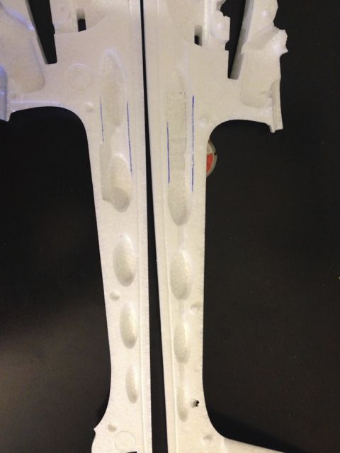
I only removed one arch support and not all the way. I took only enough away, In
wanted as much to stay for structural support. However, later when building and
mounting the components, I wish I would have bored them out a bit larger to provide
some breathing room. The way it is now, the components have to suck in their guts,
be wiggled and jiggled into place and then they can relax but with some continuous
pressure from the sides and top.
Access hatch cut out
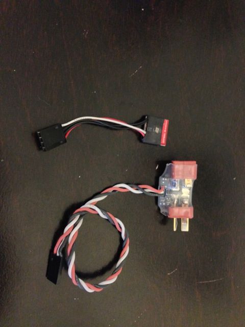
Current sensor, LC filter and BEC all wired and wrapped
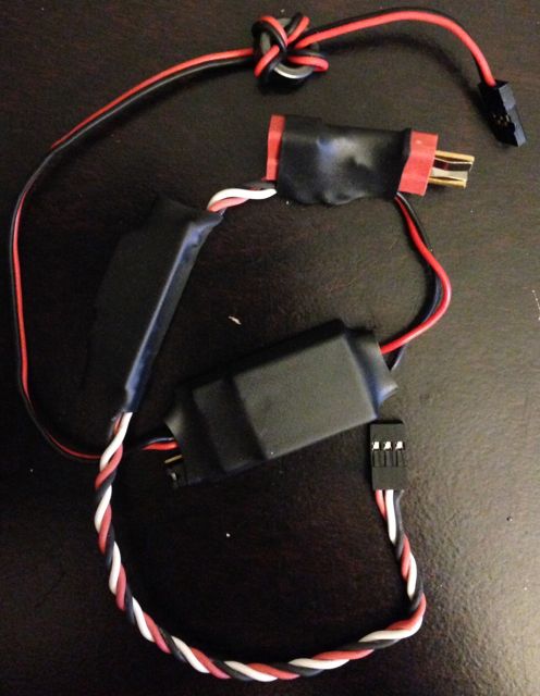
Looking back at things, I will probably wire this a bit differently sometime in
the future. As it stands now with my wiring, the OSD, Camera and VTX do not show up
in the current draw, thus their power is not computed in the overall mAH used. For
some reason I didn’t catch this prior to mounting everything.
All wired up #2
Here you can see the shielded wiring harness for the camera video/audio and video
transmitter video/audio. The shields are grounded only at the OSD.
Old Pod
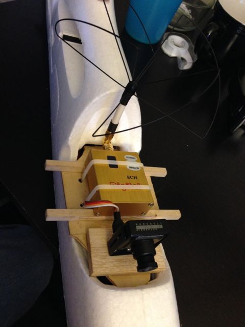
I am working on a much nicer pod with at least pan support. I am unsure if I will
be adding tilt or not. I wish to keep weight as low as possible and so far flying
when I do have tilt (Penguin) I have not used it all that much.
Inside the battery compartment
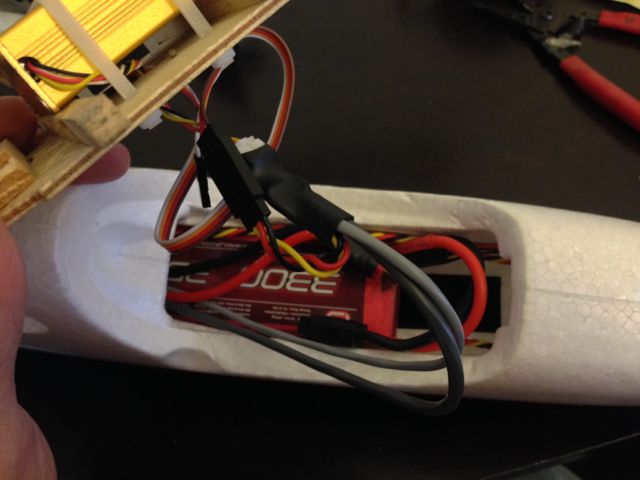
This is the part I love! There are only 3 cables to deal with… Power to the
FPV pod, Video and Audio (to and from the OSD) and a Pan Servo wire. With the new
pod, I may make a single connector for these three wires, not yet decided.
Access door mounted
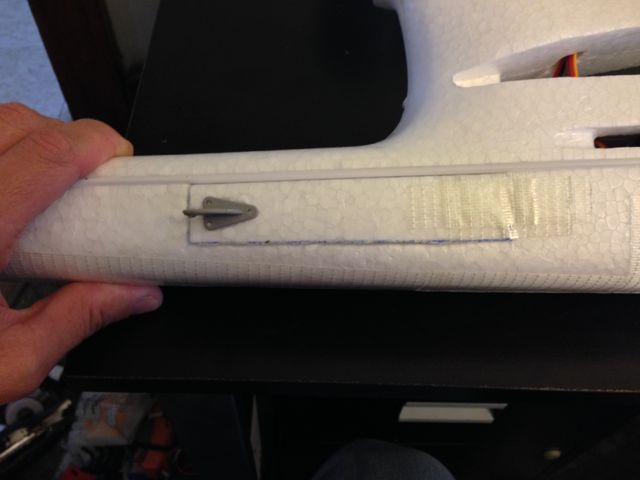
I simply used Scotch Extreme Tape as a hing in the front, an old control horn laying
around as the handle and two tiny rare earth magnets on the tail end to keep it
closed.
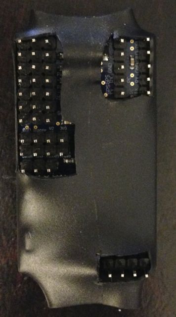
Inside the access hatch
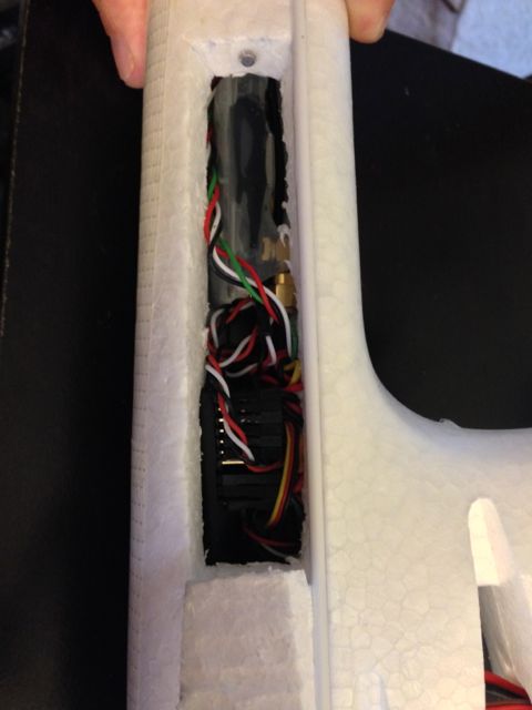
This is one area with my build I am disappointed with. Everything is neat and clean
but it was much tighter than I was anticipating. I can remove the RX and DOSD without
unwiring anything, but they fit very snuggly in the compartment. I would have rather
had a bit of extra room in there, but not this time around.
Various pictures of overall setup on the ground:


Things I would change if I were to do it again
- The tail boom compartments: I would have made them a bit larger. It is a tight
fit for the Dragon Link RX, Dragon OSD and the necessary wiring. - Current sensor wiring: Giving power to the OSD, Camera and VTX via the current
sensors + and - leads excludes them from the current draw display and mAH
computation. Since I use a shared battery, I would like to know the total load on
that battery, not just the motor. As it stands now, I do not know the full amount
of power consumed, thus I don’t know the real state of my battery.
This is something I can fix pretty easily (I believe) and will do on this
build once I get a bit more time on it. Maybe with more time I will find other
things I wish to change and can then do it at the same time.